Final Product
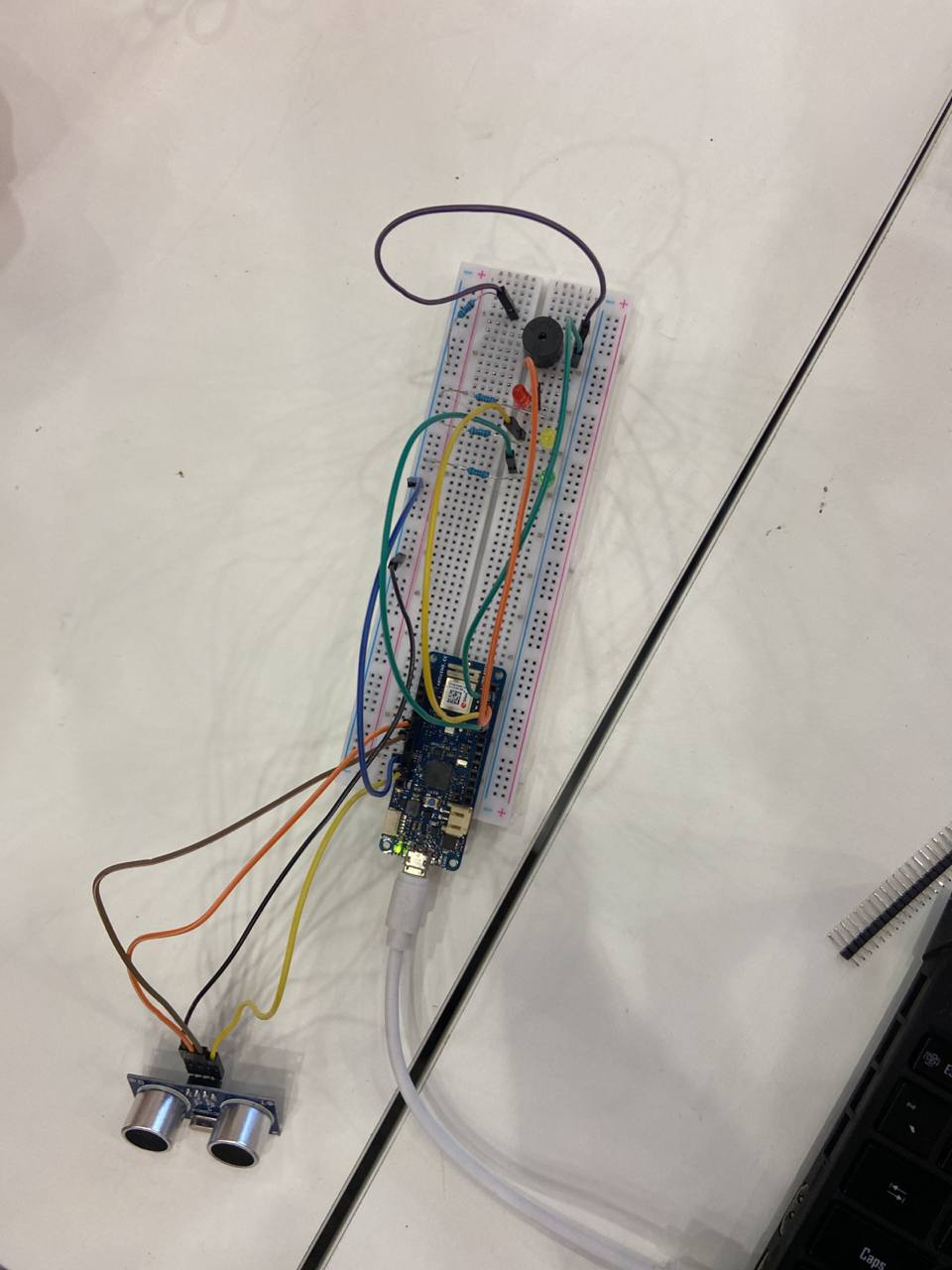
This tutorial will showcase the use of an ultrasonic sensor to detect when individuals approach an area.
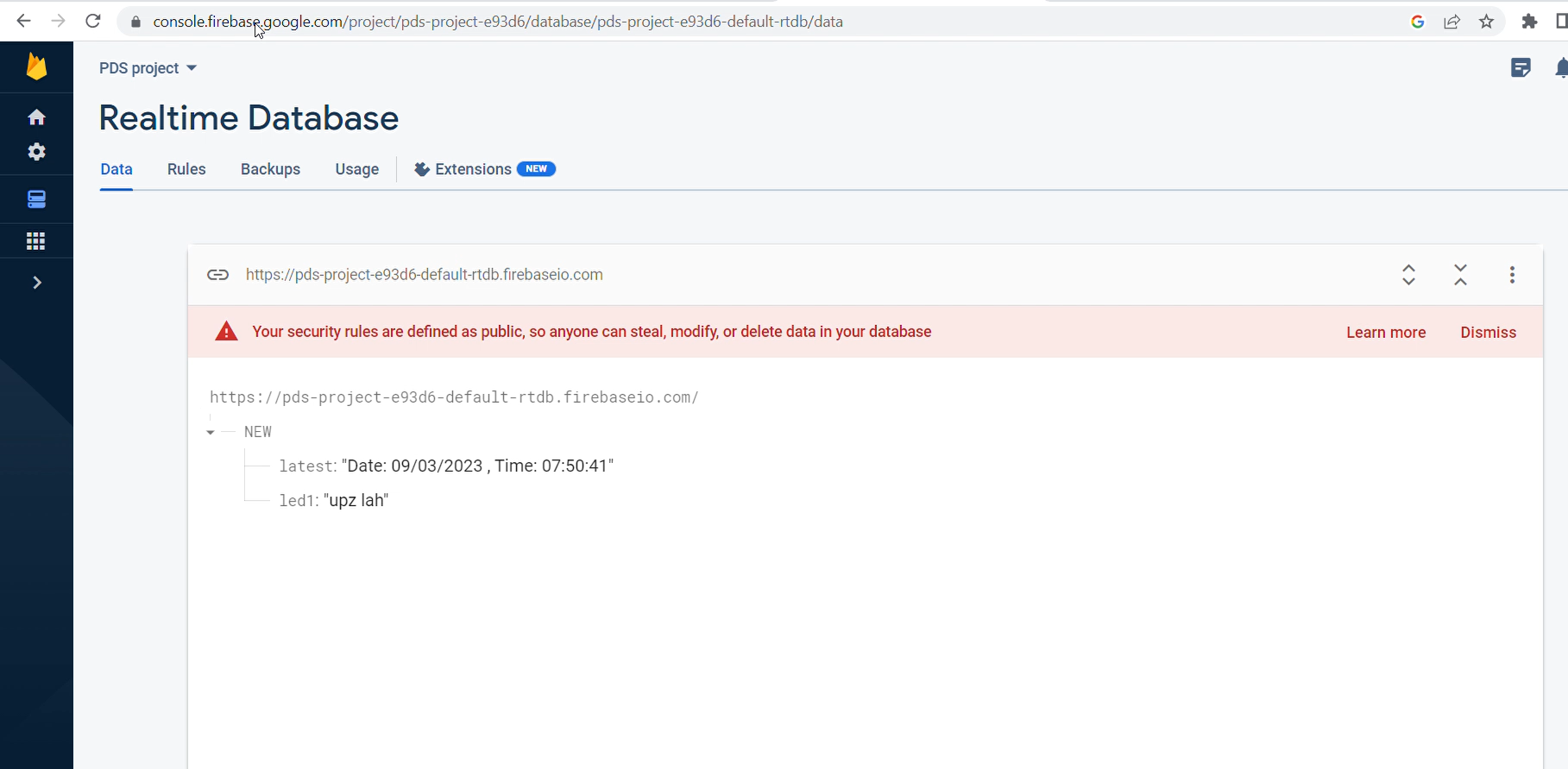
An alarm system will then be triggered and the time of detection will be uploaded to firebase.
Arduino MKR Wifi 1010 - Google Drive
https://drive.google.com/drive/folders/1T96mKVm9Y1D-OlvoJTVj7T2BHtZ3gBBi
Everytime I comeback to the DAI lab, I find that the spool of material for my 3d printer has snapped.
The snapped part of the material is too short to be used for anything productive and results in a waste of material.
This lead to the desire to create a system which deters and also logs when the last time someone went near the 3d printer is so that action can be taken.
Disclaimer: I don't think anyone is actually doing anythhing, probably just the material snapping from the humidity.
PDSvideo - Youtube
https://youtu.be/-3mcWibxiVU
Input Ultrasonic sensor reading
Output Buzzer, LED Alarm and logging of time that the alarm was tripped (in UTC timing) in firebase
Final Product

Bread Board - Shopee
Resistors - Shopee
Jumper Wires - Shopee
LEDs - Element 14
Arduino MKR Wifi 1010 - Arduino Store
KC-1206 Piezo buzzer - shopee
HCSR-04 Ultrasonic Sensor - Shopee
Arduino IDE download
Arduino IDE download
Open up arduino, click on the tools tab, go to the drop down menu for boards and open Board Manager.
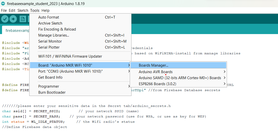
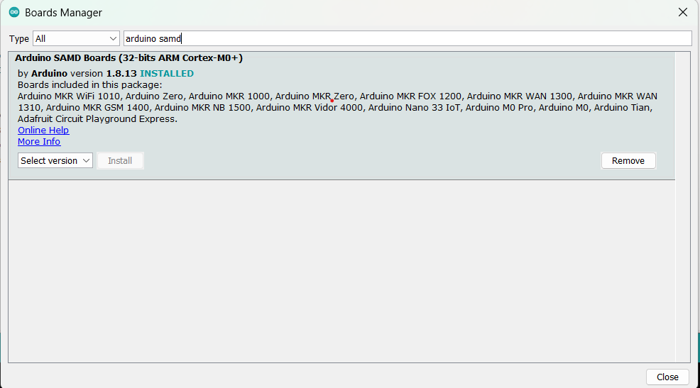
Download arduino SAMD boards if you are using the MKR Wifi 1010. You may need to download additional boards if you use other boards with a separate wifi chip.
Click on the tools tab and open Manage libraries.
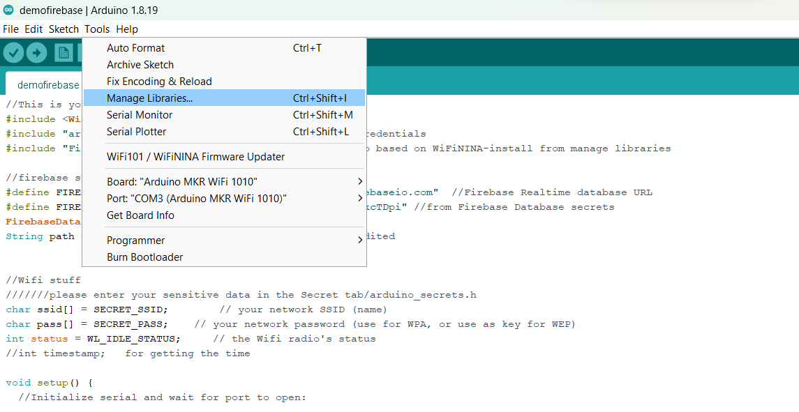
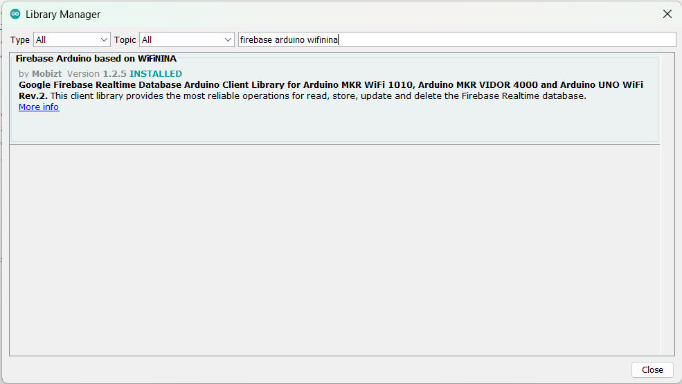
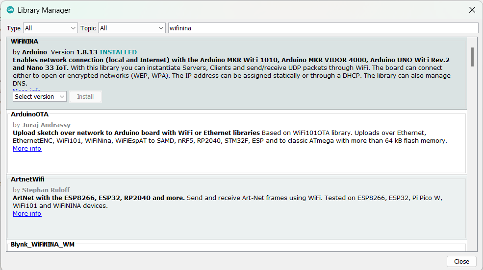
Install WifiNina and Arduino Firebase libraries.
How to use the firebase file - Youtube
https://youtu.be/LZx7xeM_peM
Do note that the code in the video is not the final code used for the project and is a simplifed file used to showcase the use of the firebase code as well as the functions written.
This code was created with reference to code provided by our professor, with rearrangments to make the code more readable and creation of functions for reading and writing to the firebase instead of being hard coded in the void loop.
Go to firebase from the following link.
Firebase
Create a new project (click add project) or use an existing project (click on one of the existing projects).
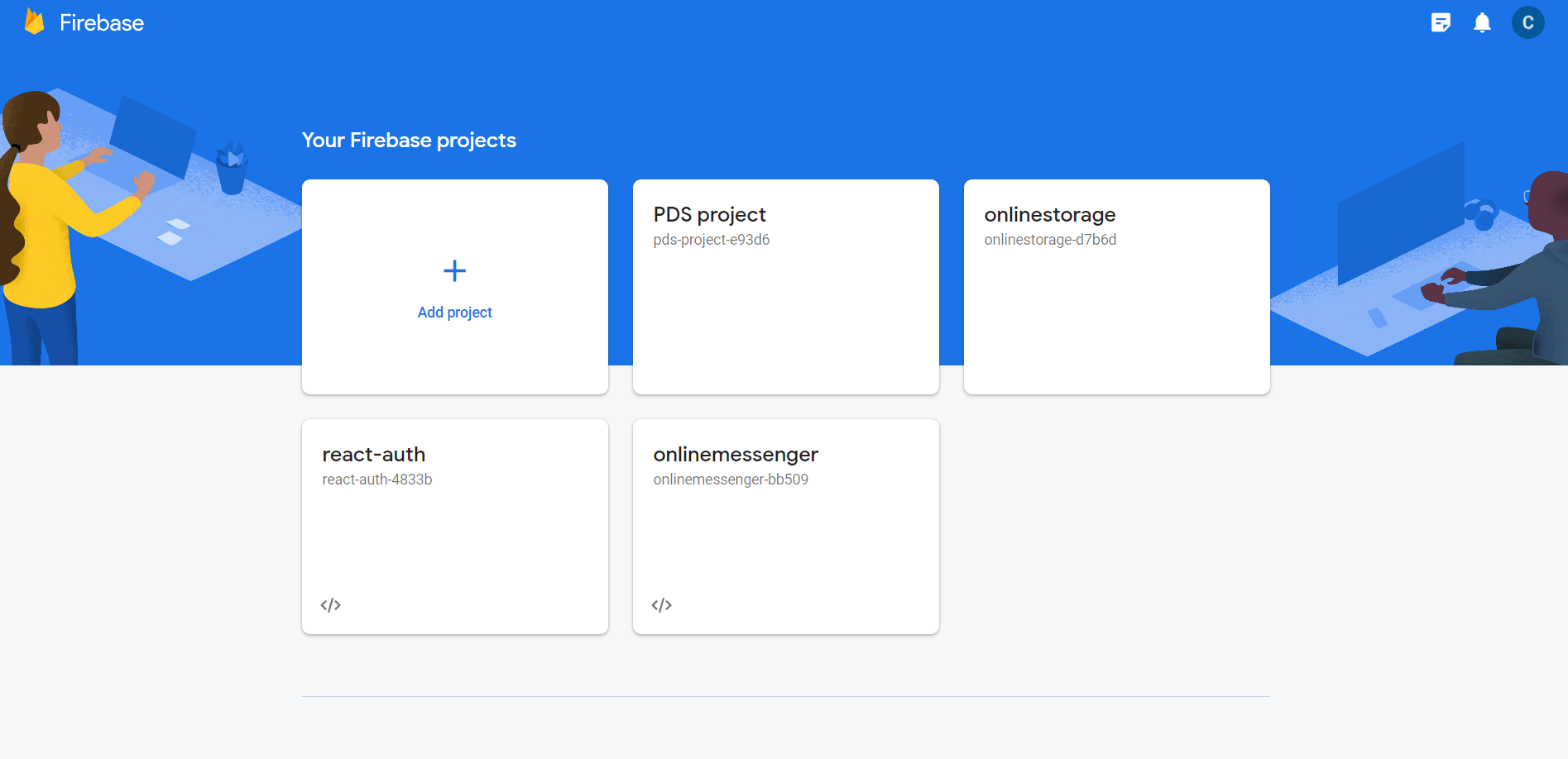
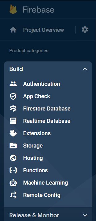
On the sidebar on the rightside of the screen, click build to drop down the menu and create a real time database.
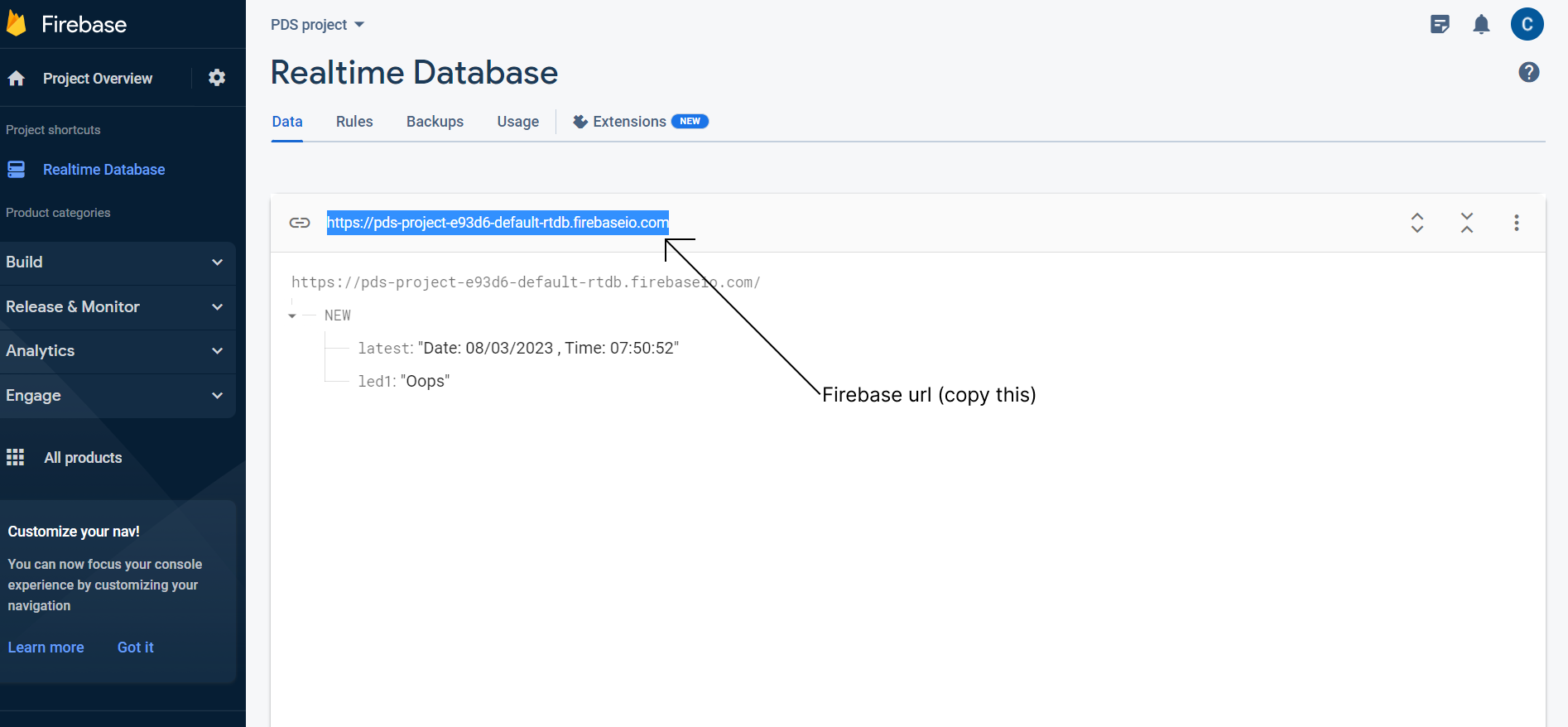
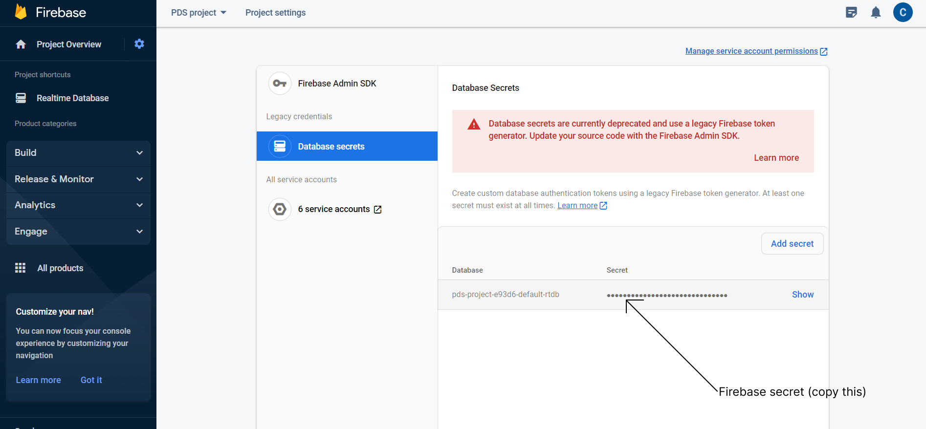
Copy the firebase url and the secrets. (Collect the firebase url from the mainpage of the realtime database. Collect the firebase secrets code from the project setting by pressing the gear in the corner, going to service accounts and database secrts.
Download the code from the google drive link
Arduino MKR Wifi 1010 - Google Drive
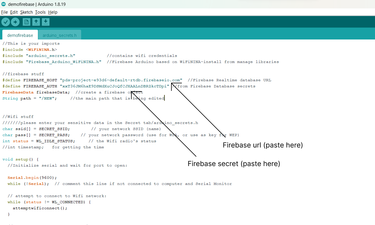
Change FIREBASE_HOST to the firebase url and FIREBASE_AUTH to the secrets copied in the prervious step.
One common mistake is pasting "https://" as well as the "/" at the back in the FIREBASE_HOST as well, make sure not to include that.
Build the circuit refering to the schematics below

If this is your first time creating an electronic circuit, follow the guide below.
First find a breadboard, you can purchase at this link below. Also make sure you have jumper wires, resistors and leds.
The breadboard connection follows the diagram below. The green lines show the holes that are connected.

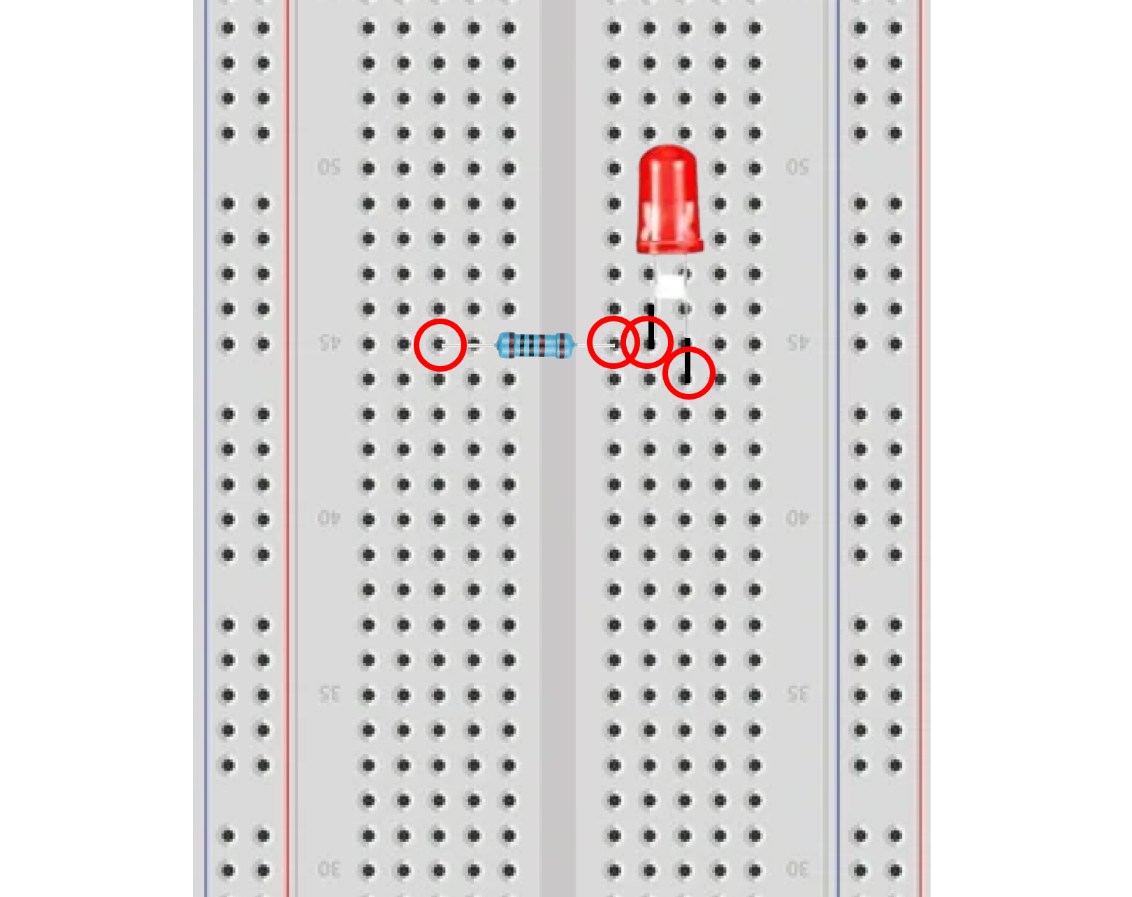
The first step is to insert a led and make a simple circuit.
For this example, we will insert a red led on two horizontal lines (make sure the 2 connections are not on the same line, if not it will result in a short circuit and it will not lightup).
Ensure that the longer leg is on the right (Anode) and the shorter leg (Cathode) is on the left.
From there insert a resistor (I used a resistor of 1k ohm resistance in the example) to connect to the line across.
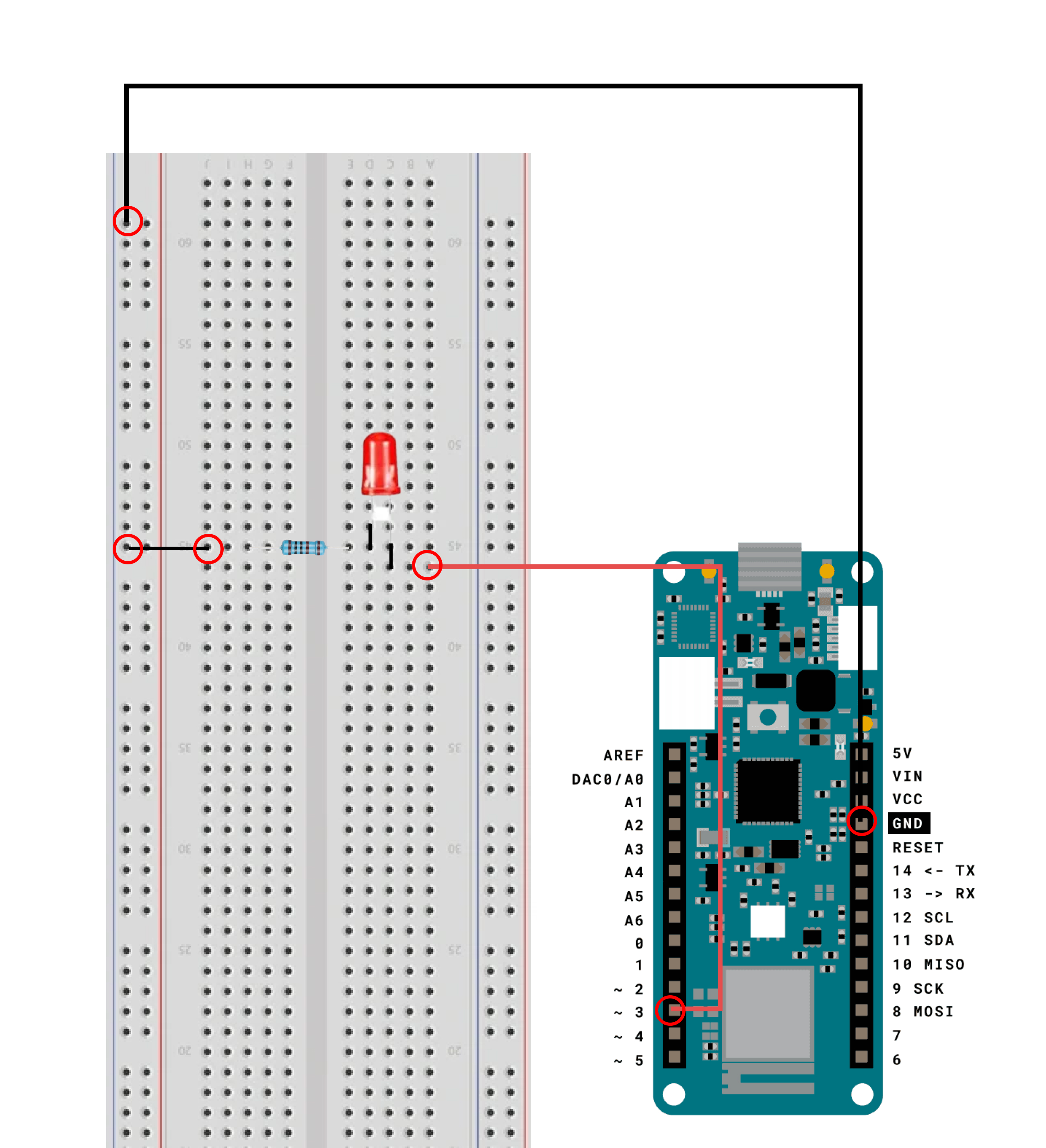
Connect the MKR wifi 1010 board to the circuit. Use a jumper wire to connect pin 3 on the right side and another wire to connect the left side to the negative rail and connect the rail to the ground (GND) port on the board.
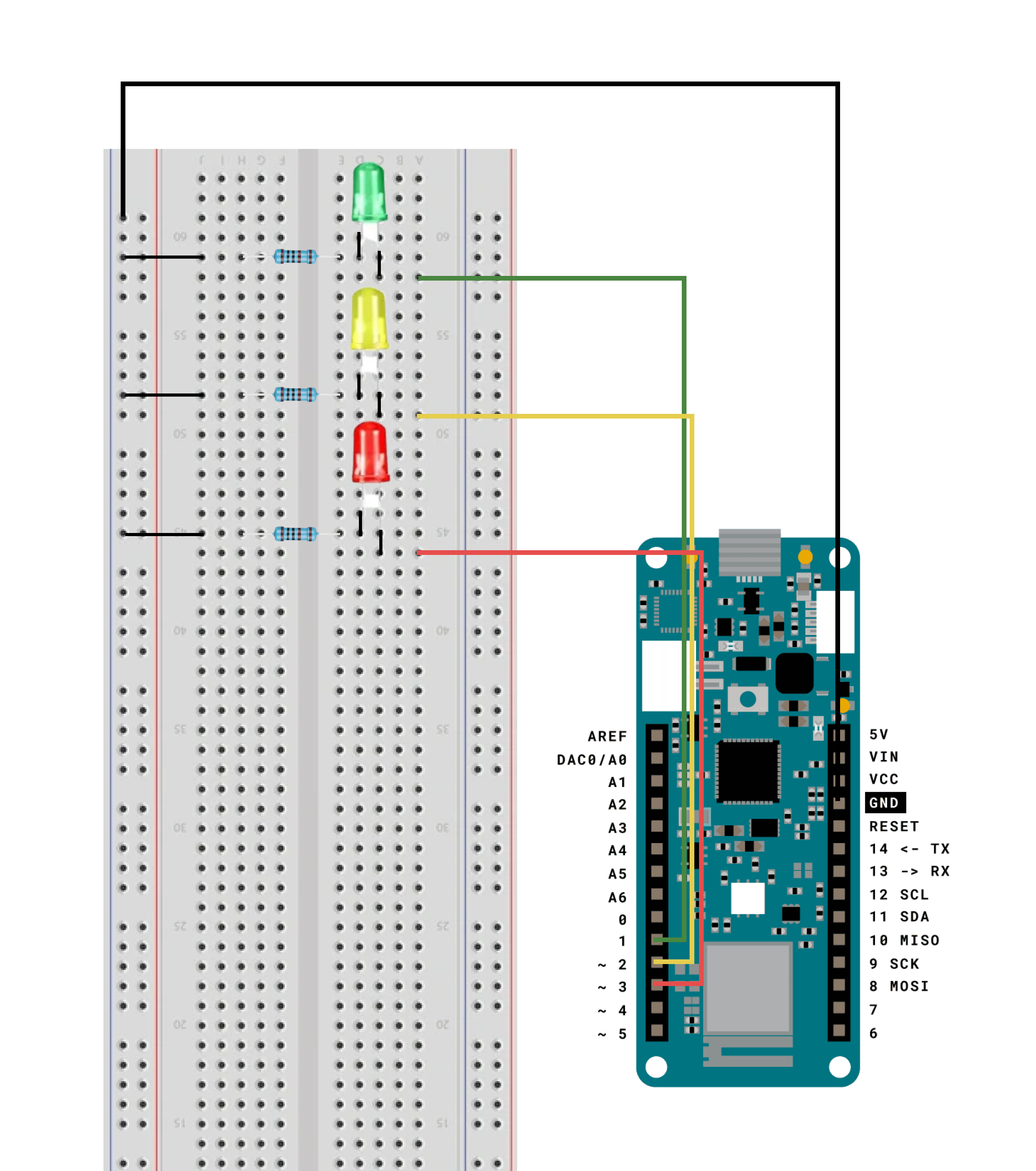
Repeat this 2 more times for the green and yellow bulb but use port 1 and 2 as the inputs instead.
Next add the buzzer, and connect it in a similar fashion to the led, but the side of the buzzer with '+' sign on it is the positive end.
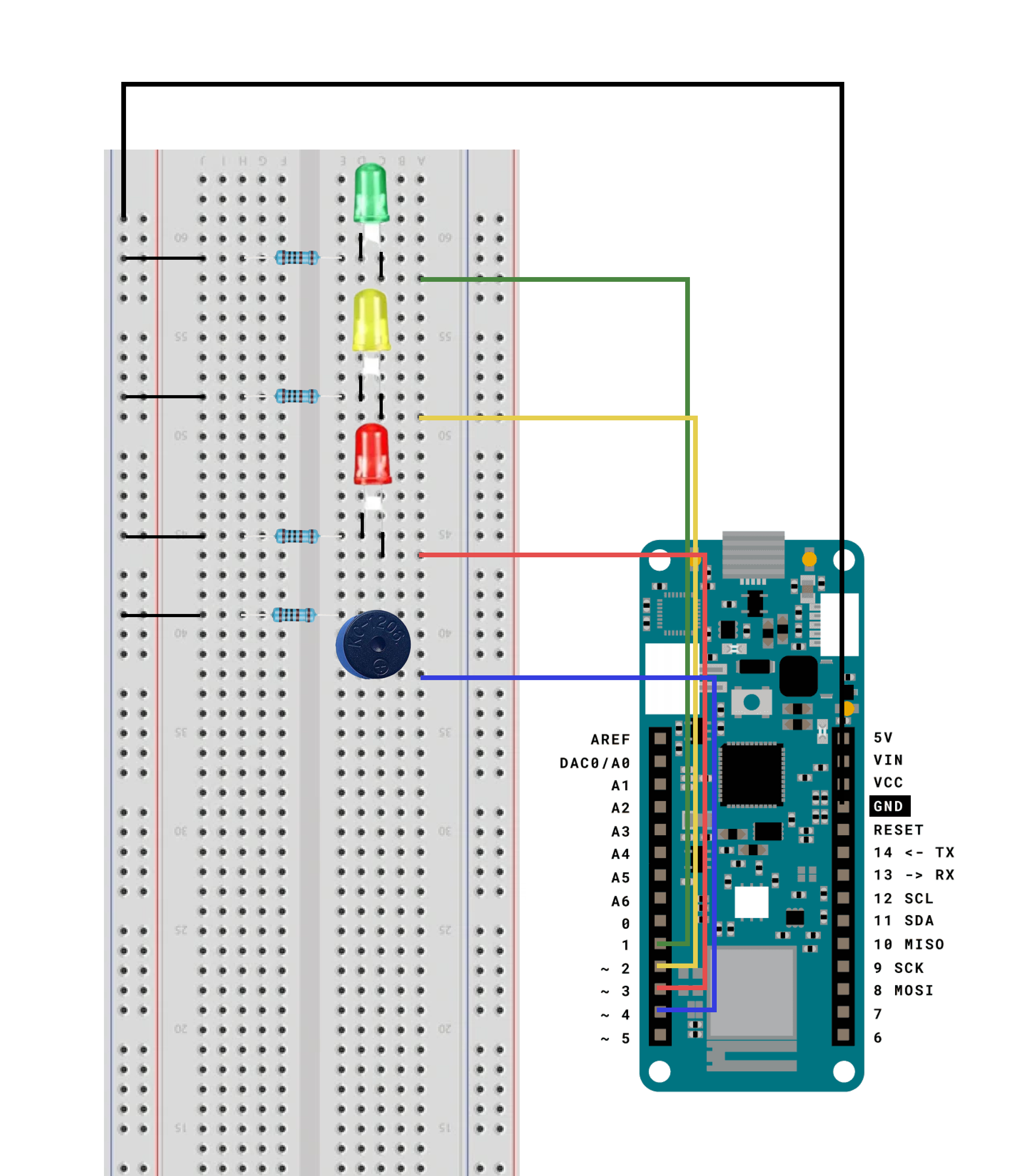
The final step is to connect the HCSR-04 ultrasonic sensor. Connect pin 13 to the trigger slot, pin 12 to the echo slot, vcc pin to vcc slot and link the ground rail to the ground pin.

Plug in the micro usb to the arduino board and upload the code. Open the Serial monitor and the database and check that the date is being logged successfully.
